
The MIDI exiter is not a standard MIDI product. It does not produce or accept MIDI note information. The purpose of the MIDI exiter is to implement a MIDI LFO. This LFO can be applied to any MIDI Control Change parameter on any MIDI channel.
The current version has a small set of parameters:
The display consists of a double 7-segment display, four yellow LEDs and one red LED. The 7-segment displays show the current value of the parameter being edited in hexadecimal numbers. If a parameter uses only one display, the other is blank. The yellow LEDs indicate which parameter is being edited:
The MIDI exiter has four user controls; three buttons and a jog wheel. The left and right buttons cycle through the five parameter edits, the jog wheel changes the current parameter and the P button saves the current parameter value in the startup value memory. The saved value is the one the parameter will have at the next startup. There is no way to recall the saved parameters other than switching the MIDI exiter off and on again.
| Overview |
 |
This second version of the board is chanced quite a bit since the previous version. The potentiometers with the ADC routines are gone as is the LCD display. The first wasn't appropriate for multi parameter input, the second to big and slow. For input a rotary encoder was developed, for output a dual 7-segment LED display and four parameter LEDs. Development was still done with AVR Studio 4. It is buggy for the 4433, but will do. |
| The processor board |  |
The main board contains a 7805 regulator, a AVR90S4433 some buffering and a CNY17 optocoupler. The parts at the lower right are an integrated serial in-circuit programmer. Device programming is done with PonyProg. |
| The rotary encoder | 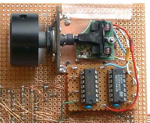 |
The rotary encoder is canibalized from an old mouse and potmeter. The mouse phototransistor signals are decoded in separate up and down pulses. Which go to INT0 and INT1. |
| Schematic | 
 |
An preliminary schematic only at the moment. The software is considered
functional complete and will be tested. Already there are ideas for
extensions, but for this a new board based on the ATmega8 will be build.
That is the idea with prototypes. Once in a while you abandon a version
and start a new one. The old version will remain functionally complete.
|
Version 2 |  |
Finding out the hard way a pertinax based construction isn't very sturdy, I changed the setup a bit and replaced the rotary encoder with an improved (real ball bearing) type. The schematics are more accurate now too, as some bugs appeared while reconnecting the boards. |
Last updated: 2003-12-27